MRI Spine Protocols

:dropcap_open:Y:dropcap_close:our pateint has radicular pain in the lumbosacral distribution that is status post-motor vehicle accident and you order a lumbar MRI. The report rendered by a board certified general radiologist concludes mild disc bulging at L5-S1. However, upon further review by both a neuroradiologist and yourself (once you have been certified and trained to interpret MRI), you realize the general radiologist erred and the scan reveals a protrusion-type herniation compressing the left L5 nerve root correlating to your pateint’s clinical presentation.
 
mrispineprotocalsfig1Herein lies multiple potential culprits for an inaccurate diagnosis. First, as I have discussed previously, general radiologists have a 42.2% error rate as reported by Lurie, Doman, Spratt, Tosteson, and Weinstein (2009), which makes it virtually imperitive that we, as practitioners, must take control of a critical component in diagnosing our pateints. At the very least, we must understand the basics of MRI spine interpretation to verify the findings or lack thereof. We also must be congnizant of the fact that we often rely on the MRI when ordering and delivering high velocity thrusts into our pateints. At this level, accuracy matters in determining a correct prognosis and treatment plan to ensure the safety of our patients when adjusting the spine. It is imperative for chiropractic.
 
A second factor in accurate MRI reporting is the precise acquisition of slices. Too many MRI technicians are not meticulous in positioning where the slices are taken and often catch too much of the end plates or the vertebrae, and sometimes do not catch the disc at all. After reviewing thousands of MRIs in the last few months, I can report that almost 75% of images are not done to the required standard, and in many cases radiologists must guess with incomplete image acquisitions. A case in point is image 1, which has both good and bad slice acquisitions. 
 
Referencing Figure 1, the slices should be through the disc and not catching the end plates or the vertebrae when diagnosing the disc. If we look at L5-S1 and slices 734, 735, and 736, you will notice that all of the slices catch the end plates and not one clean slice of the disc was acquired. If we go to the level above at L4-L5 and slices 727, 728, and 729, the top two slices are 100% through the disc (good), while 729 misses the disc entirely. Although acquisition of bone is necessary, that was not the intented purpose of that slice.
 
If we compare L5-S1 to L4-L5, it illustrates this problem in one patient. Every disc ideally should have a minimum of three clean slices through the disc without catching the end plates. There should then be slices through the bone as well to diagnose any osseous issues. The lack of clean slices is nothing more than the MRI technician “missing the target” and the radiologists accepting inferior images to interpret. In teaching hospitals, as with my patients, I demand clean slices or I mandate the center redo the scan if I feel that I am missing pathology. Should your imaging company offer 3-D technology, as mine does (a topic for another article), you can get 24 slices through one disc. However, most MRI centers do not yet have this technology available. 
 
Many will argue that, based on either the scout image or the sagittal view, it does not warrant thin slices or that thin slices will create too much signal-to-noise ratio and cause poor quality images. That is a great argument to take thick slices and result in fewer images increasing the profit margin of the imaging center. Otherwise, the argument is moot and centered on the bottom line versus quality patient care.
 
Slice thickness is another critical component of a quality MRI. The American College of Radiology (ACR) has set forth the following guidelines for maximum thicknesses:
mrispineprotocalsfig2The key to this graph is the concept “maximum” and it does not illustrate a complete sequence to ensure that most pathologies are not missed. In addition, most MRI centers tout that they are ACR accredited and that is factual. However, being ACR accredited does not mean that they use ACR guidelines in their scans. In addition, there are no regulatory standards in any state enforcing those guidelines for imaging centers. That “ruse” is quite profitable for those centers at both you and your patients’ expense because this often leads to many missed pathologies. So it also leaves you exposed to hurting your patients—caveat emptor!

According to Robert Peyster, MD, neuroradiologist and section chief of neuroradiology of State University of New York at Stony Brook Medicine who acquired his neuroradiology education at Mass General (Harvard) and has been published more than sixty times on MRI, the following sequences should be considered:

mrispineprotocalsfig3Please note that all of the scenarios involve “no gap.” They are no longer necessary with today’s technology. These recommendations exceed the ACR guidelines and are meant to do so. As I have already articulated, those guidelines are minimum standards with maximum slice thicknesses. The thinner the slice, the more you see with “volume averaging” in image acquisition.

Understanding that this article is intended to serve as a guide, I urge every DC worldwide to learn the significance of each sequence and be able to interpret MRIs (or at least the basics) to protect patients from any of the above scenarios. Dr. Peyster and other world-class specialists teach MRI to DCs at www.teachdoctors.com. This course carries a certification from the University of Bridgeport, College of Chiropractic and State University of New York at Buffalo, School of Medicine and Biomedical Sciences. This is the only program that offers a “cross certification” through both chiropractic and medical academia. Although this has had significant positive ramifications for chiropractic in the courts nationally by allowing DCs to testify as experts when challenged, the real winners are the patients.

Do not be taken advantage of by unscrupulous imaging centers when ordering MRIs. Winning through clinical excellence is the only solution and DCs now have the opportunity to learn how to interpret MRIs from the same educators who have taught thousands of medical neuroradiologists to interpret spinal MRIs. This level of clinical excellence has nothing to do with your philosophy of practice or method of delivery of care. It is purely about accurately triaging your patients with an accurate diagnosis, prognosis, and treatment plan.

References:

  1. Lurie, J. D., Doman, D. M., Spratt, K. F., Tosteson, A. N. A., & Weinstein, J. N. (2009). Magnetic resonance imaging interpretation in patients with symptomatic lumbar spine disc herniations. Spine, 34(7), 701-705.
  2. American College of Radiology (2011). MRI practice guideline for the performance of magnetic resonance imaging (MRI) of the adult spine. Last retrieved July 11, 2013 from http://www.acr.org/~/media/ACR/Documents/PGTS/guidelines/MRI_Adult_Spine.pdf

Degenerative Spondylolisthesis and Leg Pain: What’s the Connection?

figure1dsandlegpainHistory
This 60-year-old female patient presents with lower back and sciatica pain through the buttock into the posterior thigh. 
 
Diagnosis:  
Observe the extensive sclerosis and osteophyte formation occurring bilaterally at the L5/S1 facet structures. There is a degenerative anterolisthesis of L5 upon the sacrum of approximately 4 mm. No evidence of pars defects is seen at the L5 segment.
 
Degenerative Spondylolisthesis:
figure2dsandlegpain
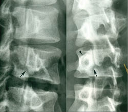
Degenerative spondylolisthesis is a type of non-spondylolytic spondylolisthesis (no pars defect). Schmorl and Junghans refer to this condition as “pseudo-spondylolisthesis” to differentiate it from cases with a neural arch defect (spondylolytic spondylolisthesis). Macnab prefers the phrase “spondylolisthesis with an intact neural arch,” which is a more accurate description.¹
 
Degenerative spondylolisthesis can affect any degenerated vertebral segment positioned within a lordotic curve. In the lumbar spine, it most commonly affects L4, with approximately 10 times more prevalence than at the L3 or L5 vertebrae. Generally, anterior displacement of the L4 vertebral body is not > 25%, and the majority of cases involve only 10-15% displacement. ¹
 
Degenerative spondylolisthesis is a forward displacement of a vertebral body secondary to extensive superior and inferior facet arthrosis. This is frequently associated with degenerative disc disease and is most commonly found at the L4 segment in females > 40 years of age (the three Fs of degenerative spondylolisthesis).¹
 
The Three F’s Of Degenerative Spondylolisthesis

  • Female
  • Fourth lumbar vertebra
  • Forty years old or older 1
The absence of a pars defect (which would increase the sagittal dimensions of the central canal) results in narrowing of the antero-posterior (AP) diameter of the spinal canal, which causes central spinal stenosis, in addition to lateral recess and neuroforaminal stenosis. The contours of the thecal sac have an hourglass or cosntrictred outline. Because the vertebral body projects anterior and inferior in relation to the disc below, a pseudo-disc appearance can be created on the CT or MRI studies.¹
 
Synovial Cyst Formation
Synovial cysts are degenerative in nature and can occur in or adjacent to degenerative facet joints. They may reach considerable size and cause localized back and leg pain. On T1-weighted images, synovial cysts may be seen as low signal intensity masses in the posterior spinal canal. They may be better delineated on T2-weighted scans because their fluid contents become hyperintense. The key to the diagnosis is their location and the proximity of the cyst to the synovial joint. Although an unusual finding, gas-filled synovial cysts have been reported. This degenerative vacuum phenomenon may be present in the apophyseal joint, and the continuity of cysts within the synovial joint can allow gas to become trapped within the cyst.¹
 
Clinical Comment And Summary:
Patients with degenerative spondylolisthesis who present with not only back pain but also ongoing leg pain that does not resolve with conservative treatment should be evaluated by an MRI scan to rule out a degenerative synovial cyst. These cysts can compress the exiting nerve root and produce unremitting leg pain. Cox has described reduction of these cysts with flexion distraction treatment as was documented by the work of Wilby on blockage of the 12 mm drainage opening from the facet joint to the ligamentum flavum as the cause of the cyst. ² Cox has reported a number of cases where there has been successful decompression of these cysts with flexion distraction treatment.3,4,5 Surgical intervention has also been recommended to remove the cysts rather than just decompress the cysts by means of puncture. Without surgical removal, the cysts often recur similar to a Baker’s cyst recurring in the knee.
 
References
  1. Yochum TR, Rowe LJ: The Essentials of Skeletal Radiology, 3rd ed., Baltimore, Williams & Wilkins, 2005.
  2. Martin J. Wilby, Robert D. Fraser, Barrie Vernon-Roberts and Robert J. Moore: SPINE, Volume 34, Number 23, pp. 2518-2524.
  3. James Cox, Chiropractic Treatment of Lumbar Spine Synovial Cysts: A Report of Two Cases, J. Manipulative and Physiological Therapeutics.28(2), Feb. 2005, p. 143-147.
  4. James Cox, Chiropractic Treatment of Lumbar Spine Synovial Cysts: A Report of Two Cases, J. Manipulative and Physiological Therapeutics.28(2), Feb. 2005, p. 143-147.
  5. L. Hazen, James Cox: Lumbar Intraspinal Extradural Synovial Cyst: A Case Study, J. Neuromusculoskeletal System, 1(4): 1993. 
Dr. Terry R. Yochum is a second generation chiropractor and a Cum Laude Graduate of National College of Chi­ropractic, where he subsequently completed his radiology residency. He is currently Director of the Rocky Mountain Chiropractic Radiological Center in Denver, Colorado, and Adjunct Professor of Radiology at the Southern California University of Health Sciences, as well as an instructor of skeletal radiology at the University of Colorado School of Medicine, Denver, CO. Dr. Yochum can be reached at 1-303-940-9400 or by e-mail at [email protected]

Dr. Alicia M. Yochum is a third generation chiropractor and 2011 Suma Cum  Laude Graduate of Logan College of Chiropractic, as well as a Registered Nurse. She is in a Radiology residency at Logan College in St. Louis, MO. She can be reached at [email protected].  

Pending Spondylolysis and/or Spondylolisthesis: What’s It All Mean?

Case History
This 18-year-old female gymnast is complaining of unilateral left-sided lumbar spine pain at the L5 level.  Standard plain film radiographs show no evidence of pathology, pars defects or spondylolisthesis.  Because this patient’s pain did not respond to conservative treatment, an MRI scan was performed for further evaluation.
 
Imaging Findings of this Patient
Observe the area of bright (white) signal intensity seen in the pedicle pars region on the left side at the L5 segment (arrows).  This is nicely demonstrated on both the axial study and the left-sided parasagittal imaging.  No true pars defects are identified at this time.  The areas of increased signal intensity in the left pedicle pars region of L5 represent bone marrow edema and a “PENDING SPONDYLOLYSIS.”  No pars defects were identified on the axial or parasagittal images.  The author (Terry R. Yochum) has coined the term “PENDING SPONDYLOLYSIS” for those patients who are developing a stress fracture prior to any actual frank separation in the bone.  If these patients continue to perform their repetitive hyperextension activities, the area where the bone marrow edema is present will cause the pars to actually fracture and separate.
 
Discussion
spondylolysisorlisthesis
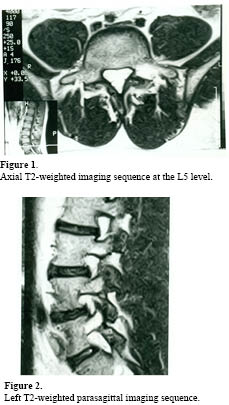
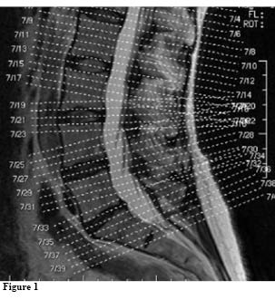
Historically, two modes of diagnostic imaging have been used to assess whether physiological activity is present and associated with the existing pars defects or “PENDING” defects.  Radionuclide bone scan imaging, particularly SPECT (Single Photon Emission Computed Tomography), has often been the examination of choice; however, it suffers from two drawbacks:  it exposes the patient to ionizing radiation and it provides very little anatomical information. Fortunately, these concerns have been addressed with the advent of MR imaging. Understanding that pars defects represent a stress fracture of the fatigue variety rather than an inherited congenital anomaly or predisposition has been a life-long quest for me (Terry R. Yochum). Having reviewed many athletes’ images, I have had the opportunity to see the proven value of MR imaging for the assessment of physiological activity that occurs adjacent to a pars defect, or that which is hidden in the region of the pars interarticularis when the defect is in fact “PENDING.”  I feel, at this point in time, that SPECT imaging is no longer the exam of choice, since there is so much more information obtained with the physiological imaging of magnetic resonance.
 
I have seen many cases where bone marrow edema adjacent to the pars or hidden within an intact pars on its way to becoming a pars defect (PENDING SPONDYLOLYSIS) has been missed on standard T2-weighted images.  A STIR imaging sequence clearly provides this information.  The STIR imaging sequences are the equivalent of fat suppression techniques or fluid-sensitive pulse sequences and significantly enhance the ability to see bone marrow edema within the region of the pars.  If a STIR imaging sequence reveals bone marrow edema adjacent to an existing pars defect or within the pars interarticularis in a “PENDING SPONDYLOLYSIS,” patients must cease participating in any sports-related activities and be placed in a Boston Overlap brace for a minimum of three to four months.  Once appropriately braced and physical activity is reduced, patients with “PENDING SPONDYLOLYSIS” usually do not develop a true bony pars defect.
 
The patient presented in this case study never developed actual pars defects and back pain was 90% reduced after being placed in a Boston Overlap brace for approximately three months.  The patient’s lower back pain was 90% better once placed at a position of anti-lordosis, which is the purpose of the Boston Overlap brace.
 
For a more detailed discussion of this condition, its imaging evaluation, treatment and prognosis, please see Chapter 5 of the new edition of Yochum and Rowe’s Essentials of Skeletal Radiology published by Lippincott, Williams & Wilkins, 2005.
 
References 
  1. Yochum TR, Rowe LJ:  Essentials of Skeletal Radiology. 3rd ed. Baltimore  MD): Lippincott, Williams & Wilkins; 2005.
Dr. Terry R. Yochum is a second generation chiropractor and a Cum Laude Graduate of National College of Chi­ropractic, where he subsequently completed his radiology residency. He is currently Director of the Rocky Mountain Chiropractic Radiological Center in Denver, Colorado, and Adjunct Professor of Radiology at the Southern California University of Health Sciences, as well as an instructor of skeletal radiology at the University of Colorado School of Medicine, Denver, CO. Dr. Yochum can be reached at 1-303-940-9400 or by e-mail at [email protected]

Dr. Alicia M. Yochum is a third generation chiropractor and 2011 Suma Cum  Laude Graduate of Logan College of Chiropractic, as well as a Registered Nurse. She is in a Radiology residency at Logan College in St. Louis, MO. She can be reached at alicia.yochum@ gmail.com.

Sacral Fractures

sacralfractures2jpg
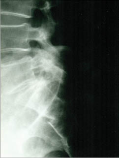
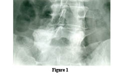
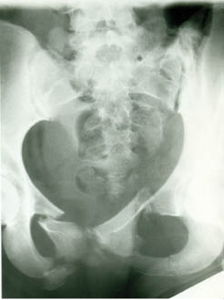
Case History:  This male patient was working on the roof of his garage when he slipped and fell 12 feet to the concrete pavement of his driveway.  He has sharp pain over his proximal sacrum. Does he have a fracture?

Diagnosis:  Note the fracture through the anterior surface of the second sacral segment creating an acute offset of its anterior cortical surface.  
 
Sacral Fractures. 
Sacral fractures usually occur as a result of a fall upon the buttocks or following a direct trauma. There are two types – horizontal and vertical.
 
Horizontal (Transverse) Fractures. These are the most common type of sacral fractures. The most common location is at the level of the third and fourth sacral tubercle, which is near the lower end of the sacroiliac joint. The fracture line is frequently difficult to identify due to overlying gas and feces. Often, a cleansing enema of the lower bowel and rectum before the radiological examination facilitates its demonstration.The lateral radiograph is usually required to demonstrate the fracture. Often, the lower segment of the sacrum may be displaced or angled forward.  (1)
 
A horizontal fracture of the upper sacrum, affecting the first or second sacral segments, may occur from falls from a height.  It is usually associated with suicidal attempts by jumping (“suicidal jumper’s” fracture).  (1)
 
Vertical Fractures. These usually occur as a result of indirect trauma to the pelvis. They are visible in the frontal radiograph but not the lateral view. The cephalic tilt-up view or a coronal C.T. scan may be necessary in order to demonstrate the vertical fracture line, which usually runs nearly the entire length of the sacrum.  (1)  The normally symmetrical transverse sacral foraminal lines should be carefully scrutinized for detection of the fracture line.
 
Isolated fractures of the sacrum are uncommon, and a diligent search for an associated fracture of the pelvic ring or symphysis pubis is often beneficial.
 
Coccygeal Fractures. Most fractures of the coccyx are transversely oriented, similar to those of the sacrum.  Seldom are they seen on the frontal radiograph; the lateral film best demonstrates this type of fracture.The fracture line is usually oblique in presentation, and slight anterior displacement of the distal coccyx is quite common. Developmental variation in the position of the distal coccygeal segment may provide some concern to the inexperienced observer.
 
Reference
1. Yochum TR, Rowe LJ: Essentials of Skeletal Radiology, 
3rd ed.,Lippincott, Williams & Wilkins, Philadelphia, PA, 2005.
 
Dr. Terry R. Yochum is a second generation chiropractor and a Cum Laude Graduate of National College of Chi­ropractic, where he subsequently completed his radiology residency. He is currently Director of the Rocky Mountain Chiropractic Radiological Center in Denver, Colorado, and Adjunct Professor of Radiology at the Southern California University of Health Sciences, as well as an instructor of skeletal radiology at the University of Colorado School of Medicine, Denver, CO. Dr. Yochum can be reached at 1-303-940-9400 or by e-mail at [email protected]

Dr. Alicia M. Yochum is a third generation chiropractor and 2011 Suma Cum  Laude Graduate of Logan College of Chiropractic, as well as a Registered  Nurse. She  started her Radiology Residency at Logan College in  April 2012. She can be reached at [email protected].  

Unilateral Spondylolysis

Case History: This is a young college student who plays competitive basketball and is complaining of chronic mid lumbar spine pain. She hurts on hyperextension and has some relief on flexion. The specific diagnosis is?

unilateralspondylolysis

Figure 1.   
Diagnosis: 
Unilateral Spondylolysis (pars defect) with contralateral sclerotic hypertrophy of the opposite pedicle.

Unilateral Spondylolysis 
Spondylolysis may involve only one pars interarticularis of a single vertebra and may allow a 5 – 10% anterolisthesis.  Unilateral spondylolysis may result in a compensatory stress hypertrophy of the contralateral pedicle in the region of the pars.  (1)  This compensatory hypertrophy is manifested radiographically by a contralateral, dense, sclerotic, enlarged pedicle and pars region.  This appearance may mimic osteoid osteoma, osteoblastoma, or osteoblastic metastatic disease, which are common at this site.  Agenesis of the pedicle may also show the same stress hypertrophy of the contralateral pedicle and pars region.  The key differential sign is the presence of a unilateral pars defect.  Regression of the compensatory bone changes may occur, should a stress fracture develop on the same side as the dense pedicle, resulting in bilateral spondylolysis and thereby equalizing the weight bearing and reducing the stress within the involved spinal motion segment. (1)
 
A MRI scan with STIR (fat suppression or fluid sensitive imaging) imaging will be positive at the active lesion demonstrating bone marrow edema (BME).  That may be the unilateral pars defect or the contralateral sclerotic enlarged pedicle or both.  If active, these areas would also be “hot” on a SPECT bone scan. These physiological studies drive the patient management.  (See chapter 5 of Yochum & Rowe).
 
Reference:
 
1. Yochum TR, Rowe LJ:  Essentials of Skeletal Radiology, 3rd ed., Lippincott, Williams & Wilkins, Philadelphia, PA, 2005.

Dr. Terry R. Yochum is a second generation chiropractor and a Cum Laude Graduate of National College of Chi­ropractic, where he subsequently completed his radiology residency. He is currently Director of the Rocky Mountain Chiropractic Radiological Center in Denver, Colorado, and Adjunct Professor of Radiology at the Southern California University of Health Sciences, as well as an instructor of skeletal radiology at the University of Colorado School of Medicine, Denver, CO. Dr. Yochum can be reached at 1-303-940-9400 or by e-mail at dcrad099@ aol.com

Dr. Alicia M. Yochum is a third generation chiropractor and 2011 Suma Cum  Laude Graduate of Logan College of Chiropractic, as well as a Registered  Nurse. She is starting her Radiology Residency at Logan College in  April 2012. She can be reached at alicia.yochum@ gmail.com.  

Digital X-ray Solutions for Chiropractic

:dropcap_open:X:dropcap_close:-rays play an important role in determining the exact cause for many health complications in patients. The advancements in radiography are allowing physicians to pinpoint the exact cause of complications through high quality output in a matter of seconds. As a chiropractor, it is important to determine what part of the body is causing the trouble, and you can do that easily with digital radiography. You can choose one of three digital X-ray options to set up in your chiropractic clinic. 

Computed Radiography

digxraysolutionComputed radiography (CR) is the closest process to traditional radiography because it still includes the use of X-ray cassettes and films, albeit in a different form. Instead of the traditional X-ray film, computed radiography makes use of a reusable phosphor plate. After taking each image, the plate will be processed through a scanner that then erases the image so that the plate can be used again. As the process of obtaining imaging is very similar to traditional radiography, computed radiography also takes the same time to finish one cycle.

As the images are now digitized, the need for chemicals, X-ray films and a darkroom does not exist. Computed radiography equipment requires regular maintenance and replacement as the moving parts tend to wear out after prolonged use.

Charge-Coupled Device

The charge-coupled device is the closest arrangement to flat panel digital X-rays. They produce fairly high quality imaging using an extensive setup of cameras and mirrors. Some elaborate arrangements are known to contain almost 192 cameras. Charge-coupled device (CCD) systems were extremely popular a while back because they produced results closest to those from flat panel detectors for a fraction of the cost. CCDs are still highly preferred among physicians and clinics because they are cost effective. By choosing the right model, you will get high quality imagery with lower maintenance costs than computed radiography.

Although they are much cheaper, charge-coupled devices are bulky and occupy a lot of space. They also require high frequency generators to produce high quality images. The hundreds of cameras attached to the device need to be recalibrated every few weeks to ensure that there are no blank spaces in the output. A huge advantage CCD has over computed radiography is the response time. Each image can be captured and digitized in just about five seconds.

Flat Panel Digital X-ray

Although flat panel digital X-ray detectors were considered to be too pricy a few years ago, they are now more affordable and popular than ever. Most hospitals are switching to flat panel detectors because they produce the best results in the shortest amount of time. These detectors are also the safest for patients as they emit the least amount of radiation. Flat panel detectors (FPDs) are known to produce the most detailed images, which help chiropractors detect even the smallest inconsistencies in the body. As they contain no moving parts, FPDs are long-lasting with an average lifespan of at least one million exposures. Unlike CCDs, flat panel detectors do not require high frequency generators to achieve excellent image quality. Taking only two to five seconds for each image, an FPD’s only drawback is its slightly higher price than CR or CCD. However, a flat panel upgrade is the most economical long-term digital X-ray solution in my opinion.

Ryan has been involved in the X-Ray business for 15 years. He started doing X-Ray service and is now a top sales producer at Viztek based in Garner NC. The evolution of Digital X-Ray imaging has created numerous opportunities for streamlining medical practices throughout the country. Ryan specializes in converting Analog customers to a completely Digital Imaging solutions.www.Viztek.net

Melorheostosis

melorheostosis[Case History]

This male patient has a history of multiple traumas to his humerus.  Are these radiopacities exuberant callous formation from hematoma?

Diagnosis:  The answer is no!! This is a rare sclerotic skeletal dysplasia referred to as “MELORHEOSTOSIS”.

General Considerations

Melorheostosis is a rare, sclerosing bone dysplasia that was first described in 1922 by Leri and Joanny.  Synonyms include Leri type of osteopetrosis, osteosis eberneizzante monomelica, and flowing hyperostosis.  The name melorheostosis is of Greek derivation, meaning limb, flow, and bone, and aptly describes the hyperostotic appearance that has been likened to wax flowing down a lighted candle.

Radiologic Findings 

Cortical thickening in a streaked or wavy pattern is the most marked roentgen feature.  In children the hyperostosis is primarily endosteal; in adulthood, periosteal bone deposition is more dramatic. (1) The radiographic findings appear to reflect developmental errors at the sites of intramembranous and enchondral bone formation. (1) The hyperostotic bone protrudes under the periosteum and usually follows along one side of a long bone.   Endosteal involvement may encroach upon the medullary space.   Bony masses resembling osteochondromas extend into adjacent articulations.  

:dropcap_open:Bone scintigraphy shows increased tracer uptake in the involved area.:quoteleft_close:

Involvement of the carpal and tarsal bones resembles the multiple bone islands that are seen in osteopoikilosis.  In the pelvis and scapulae (flat bones) the sclerotic bone may be in the form of dense radiations from the joint.  Heterotopic bone formation and soft tissue calcification are encountered and may lead to joint ankylosis.  Bone scintigraphy shows increased tracer uptake in the involved area.  A number of other disorders have been found in association with melorheostosis.  These include linear scleroderma, osteopoikilosis, osteopathia striata, neurofibromatosis, tuberous sclerosis, and hemangiomas. (1)

Dr. Terry R. Yochum is a second generation chiropractor and a Cum Laude Graduate of National College of Chi-ropractic, where he subsequently completed his radiology residency. He is currently Director of the Rocky Mountain Chiropractic Radiological Center in Denver, Colorado, and Adjunct Professor of Radiology at the Southern California University of Health Sciences, as well as an instructor of skeletal radiology at the University of Colorado School of Medicine, Denver, CO. Dr. Yochum can be reached at 1-303-940-9400 or by e-mail at [email protected]

Dr. Alicia M. Yochum is a third generation chiropractor and 2011 Suma Cum Laude Graduate of Logan College of Chiropractic, as well as a Registered Nurse.  She is starting her Radiology Residency at Logan College in April 2012.   She can be reached at [email protected].

Reference: 1.Yochum TR, Rowe LJ:  Essentials of Skeletal Radiology, 3rd ed., Williams & Wilkins, Baltimore, Maryland, 2005.

Fractures of the Pubis and Ischium

pubisandischium[Case History]
This patient presents following severe trauma to the pelvic region after a motorcycle accident.
 
Diagnosis:  This patient has bilateral fractures of the superior and inferior pubic rami which has been referred to as a STRADDLE FRACTURE. Fortunately, this patient had no injury to the bladder, as bladder trauma is often present with fractures such as this. Of incidental notation is a bilateral transitional segment at the lumbosacral junction with a unilateral accessory joint articulation.
 
Straddle Fractures
The straddle fracture or comminuted fracture of the pubic arches is the most common type of unstable fracture of the pelvis. This double vertical fracture involves both superior pubic rami and ischiopubic junctions bilaterally. The central fracture fragment is usually displaced posterosuperiorly, placing pressure upon the ventral surface of the bladder. Twenty percent of these patients have bladder rupture and urethral tear which may require diagnosis via urethrography and cystography.1
 
Bucket-Handle Fracture
The bucket-handle fracture represents a fracture through the superior pubic ramus and ischiopubic junction on the side opposite the oblique force of impact to the pelvis. A fracture or dislocation of the sacroiliac joint on the side of impact is part of the injury. This fracture is usually the result of an automobile or auto/pedestrian accident. The pubic component of the fracture is usually displaced inward and superiorly. Associated injuries to the abdominal viscera, head and thorax may be present.1
 
Avulsion Fractures
Symphysis Pubis.  Severe injuries of the major adductor muscles cause a tearing of bone from the superior or inferior pubic rami near the pubic articulation. This injury is common in soccer players.
 
Ischial Tuberosity (Rider’s Bone).  This type of fracture represents an avulsion of the secondary growth center (apophysis) for the ischial tuberosity as a result of a forceful contraction of the hamstring group of muscles. With healing, an unexplained overgrowth of the avulsed apophysis occurs, often leaving a wide radiolucent gap between the avulsed fragment and the parent ischium.  
 
This overgrowth may be the effect of hyperemia upon the ischial apophysis. Occasionally, the avulsed ischial apophysis may assume a size larger than the parent ischium. This large overgrowth should not be confused with an extraosseous neoplasm. Usually, the patient’s history of a previous severe hamstring injury and the fact that the lesion is asymptomatic secures the proper diagnosis.  
 
These fractures are seen most commonly in cheerleaders and hurdlers. The residual bony fragment has been called “rider’s bone,” because a high percentage of these lesions occur in horseback riders as a result of chronic stress.
 
Dr. Terry R. Yochum is a second generation chiropractor and a Cum Laude Graduate of National College of Chi­ropractic, where he subsequently completed his radiology residency. He is currently Director of the Rocky Mountain Chiropractic Radiological Center in Denver, Colorado, and Adjunct Professor of Radiology at the Southern California University of Health Sciences, as well as an instructor of skeletal radiology at the University of Colorado School of Medicine, Denver, CO. Dr. Yochum can be reached at 1-303-940-9400 or by e-mail at [email protected]
 
Dr. Alicia M. Yochum is a third generation chiropractor and 2011 Suma Cum Laude Graduate of Logan College of Chiropractic, as well as a Registered Nurse.  She is starting her Radiology Residency at Logan College in April 2012.   She can be reached at [email protected].
 
Reference: 1.Yochum TR, Rowe LJ:  Essentials of Skeletal Radiology, 3rd ed., Williams & Wilkins, Baltimore, Maryland, 2005.


Digital X-ray: Do I Need One in My Office?

:dropcap_open:S:dropcap_close:o, you are considering “transforming” your practice? Or maybe starting a brand new or satellite office? What are some of the things you should keep in mind in making decisions on just what your practice will offer? What should it look like? What kind of vibe would you like it to put out? And how does the decision of installing digital x-ray (DXR) affect your practice? 
 
As they say, there are “many ways to skin a cat.” Each practice is a reflection of its doctor; there is no one right way to operate a practice. That being said, generally speaking, most “successful” practices today should seek to: 
  1. medicalrecordsfilesAppear modern, cutting edge, and up-to-speed with other health care practices. Patients are turned off when walking into a practice that appears to be circa 1975. They simply don’t feel comfortable with a “tired” atmosphere, complete with old adjustment tables with torn padding. 
  2. Offer technology that provides convenience to the patient, in terms of comfort, functionality and time savings. As “Larry the Cable Guy” would say, “Git er done.” More than ever before, people are busy and don’t have the luxury of taking an inordinate amount of time for an office visit. If an appointment takes too long, they will stop coming, period. 
  3. Give a patient confidence that the technology employed is state-of-the-art. No one wants to be treated by any health care professional if they think there are better protocols and/or technologies that could be utilized.  Is your patient education a VCR tape on an old, low resolution TV? That probably won’t cut it.
  4. Take advice and follow models of other successful practices. Once the wheel was invented, you could pretty much assume that the wheel was a great idea and should be utilized. If you see a true (with the same type of practice in the same type of neighborhood) peer of yours successfully implementing a new technology or protocol, you don’t need to be a “doubting Thomas” – you can jump-start your own advancement by learning from the successful model of others. 
How does this apply to DXR?
As you are making decisions regarding your new or “re-invented” office, you would be well-advised to consider whether incorporating DXR is a quality fit for you and your practice. And I will say that DXR is not a fit for every doctor, so I am in no way asserting that DXR is a no-brainer for all chiropractors, because it simply isn’t. However, for those practices that fit the profile, DXR offers great benefits to not only the doctor, but to the patient as well. 
 
Mr. Green Jeans
Obviously, we live in a world that is increasingly focused on being “green” and that trend is only going to intensify as time passes. Young people are more aware of acting in a planet-friendly manner, more so than baby boomers, etc. so “being green” is not a fad that will ever disappear. It is not a “pet rock,” so to speak, but a lasting trend that will be ever-increasing. (If you aren’t old enough to understand the “pet rock” analogy, my apologies.) 
 
:dropcap_open:An office utilizing flat-screen monitors and the like generally will give the impression of a more cutting-edge practice.:quoteleft_close:
One of the features that DXR contributes is the fact that it eliminates the toxic odor of chemicals present when you are using a film x-ray unit. People are more sensitive than ever to things like a chemical odor and going digital completely eliminates that negative presence.
 
Less radiation exposure for everyone
Using DXR reduces the exposure to harmful radiation, which the public is more aware of than ever. With cancer on virtually everyone’s minds, the patients are generally very leery of exposure to radiation and will appreciate having digital technology as opposed to exposure to traditional x-rays.  
 
Time is money
Not only does going with DXR save time for the doctor, but it also saves the patient’s time as well, and they will appreciate that. You get your images instantly, as opposed to waiting for film to develop, or, of course, sending the x-rays off to another party. Also, if you need a re-take, you also know that immediately and without additional costs, as you are not using film or chemicals in the first place. Additional x-rays cost virtually nothing. You can take them until you get what you need, in terms of images that display the needed elements. 
 
Additionally, if your patient wants a copy of the x-ray, you can easily hand him a computer disk or email the image, while you have your copy of the image forever. When using film, you typically have only one copy, so you can’t give out a copy to your patient without risking your own image. 
 
digitalxrayvsfilmPatient education, compliance and retention
Giving your patient an image of their spine helps with patient education, compliance and retention – all at no additional cost with each image you hand out. This allows the patient to more fully understand, and retain, the reality of their condition. And a better educated patient is a more likely retained patient. 
 
Expert analysis on-hand
You will have to check with each individual DXR vendor, but some offer a radiologist on-hand to help analyze images, which you can easily email. When in doubt, the guidance of a radiologist to interpret digital images can be invaluable, and, in some cases, costs you no additional charges. When in doubt, check with your radiologist, at no additional expense. 
 
Developing a high-end image
In practice, you are not only competing with other chiropractors, but you are also being compared to all other health care practices in general. We know that MDs, etc. generally have offices that reflect an upper-scale, high-end image. If patients visit a chiropractor and the office is full of antiquated technologies – including a film-based x-ray unit, it will cause the patients to conjure a poor image of the practice.  An office utilizing flat-screen monitors and the like generally will give the impression of a more cutting-edge practice. Yes, it is true that chiropractors encourage an image of being non-surgical and have an aversion to using drugs — unless absolutely necessary – but the two are not mutually exclusive. In other words, you still want a practice that appears somewhat sleek and modern while not advocating allopathic medicine in general. 
 
Extra room to roam
Eliminating your film-based x-ray equipment will allow for additional space in your office. Most doctors of chiropractic struggle to make do with the square footage of their office space; there is a fine line between paying for space and having enough room for not only a waiting room, treatment rooms, etc., but also some space for retail products such as pillows, topicals, in-home rehab, etc. When you convert to DXR, you free up space otherwise used for storing images, film, chemicals and the like. Most chiropractic offices need every square inch they can find and going DXR gives you that little bit of extra space that might make a difference. 

Andrew Cheesman is Sr. VP Marketing and Sales for RF System Lab North America, based in Lincoln, Nebraska. Their head office is based in Nagano, Japan. They have over 2,000 users in the US and several thousands worldwide. They are now the largest digital retrofit company in the world. You can reach them at 800-905-1554 or visit www.rfamerica.com or email [email protected].

Anomalies of the C-1 Posterior Arch

c1posarch[Case History]

This young adult was in a car accident and has suboccipital pain. Do you see a fracture?

Agenesis of the Atlas Posterior Arch

Synonyms. Aplasia or congenital absence of the posterior arch.

Description. Lack of ossification of the posterior arch of the atlas may be complete and bilateral, may be purely unilateral, or may manifest as small clefts (i.e., spina bifida).  Dense fibrous connective tissue remains at the site devoid of ossification.  Ossification of the posterior arch of the atlas is normally present at birth, with union visible by 6 years of age.

Clinical Features. Pain or neurological complications are rare.  Atlantoaxial instability has been described.  There is occasional association with C2-C4 block vertebrae and Klippel-Feil syndrome.  Spinal stenosis may also occur.   Absence of the posterior arch needs to be differentiated from occipitalization, osteolytic metastases, aneurysmal bone cyst and osteoblastoma.  Differentiation from fractures, aggressive bone destruction, and occipitalization must be made with confidence, which may require CT or even MRI investigations.

Radiologic Features. The lateral view is the best projection for identifying the various forms of aplasia.  Oblique views are also of assistance in determining unilateral aplasias and clefts.  Thin-section CT is the technique of choice for determining the extent of aplasia and providing accurate differential diagnosis.  MRI is indicated if a neurological deficit is present.

Bilateral Posterior Arch Agenesis. The characteristic triad of findings with bilateral posterior arch agenesis is absence of the atlas posterior arch, union of the posterior tubercle to the axis spinous process (axis megaspinous sign), and compensatory enlargement and sclerosis of the anterior arch.  Occasionally the posterior tubercle will remain visible in normal position (Keller type aplasia).   Hypertrophy of the posterior atlantoaxial ligaments may produce spinal canal stenosis and be a factor for cord injury after trauma.

Unilateral Posterior Arch Agenesis (Hemi-Atlas). With unilateral posterior arch agenesis, absence of half of the posterior arch is uncommon.  The condition is best determined on the AP open mouth view and CT.

Isolated Clefts of the Posterior Arch. Isolated clefts of the posterior arch are most common in the midline posteriorly (posterior rachischisis, spina bifida occulta), accounting for 97% of arch clefts, with only 3% occurring elsewhere.  The second most common site is at the junction zone of the posterior arch with the lateral mass, where the vertebral artery passes over the arch (vertebral artery sulcus cleft).  These clefts range in size from 1 to 5 mm; have smooth, corticated opposing margins; and are best seen on oblique and slightly off-lateral projections.

Hypoplasia of the Posterior Arch. Two forms of hypoplasia of the posterior arch are described: thin and short.

  • Thin posterior arch. The width of the posterior arch is thin and attenuated maximally at the vertebral artery sulcus.  An association with Turner’s syndrome and gonadal dysgenesis has been suggested.  It may be a factor for fracture at this site after trauma.
  • Short posterior arch. The atlas posterior arch is thick and bulky, and the diameter of the spinal canal is diminished.  A described tandem finding is a thick, bulky dens that may contribute to symptomatic spinal stenosis.  The incidence of symptoms increases with age or may be triggered by minor trauma.  An association with patients of Asian origin has been implicated.


Dr. Terry R. Yochum is a second generation chiropractor and a Cum Laude Graduate of National College of Chiropractic, where he subsequently completed his radiology residency. He is currently Director of the Rocky Mountain Chiropractic Radiological Center in Denver, Colorado, and Adjunct Professor of Radiology at the Southern California University of Health Sciences, as well as an instructor of skeletal radiology at the University of Colorado School of Medicine, Denver, CO. Dr. Yochum can be reached at 1-303-940-9400 or by e-mail at [email protected]

Dr. Alicia M. Yochum is a third generation chiropractor and 2011 Suma Cum Laude Graduate of Logan College of Chiropractic, as well as a Registered Nurse.  She is starting her Radiology Residency at Logan College in April 2012.   She can be reached at [email protected].


Reference: 1. Yochum, T.R., & Rowe, L.J. (2005).  Essentials of Skeletal Radiology, 3rd ed. Baltimore, MD: Williams & Wilkins.